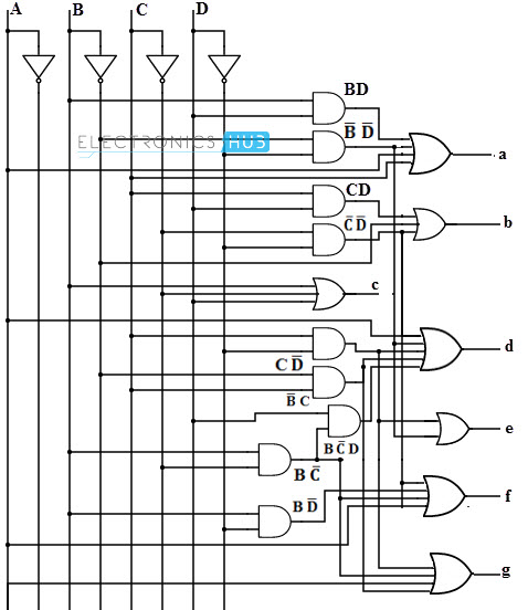
If I am doing both digital and analog (LED rings) then using 60 stage ring counters gets a bit complex, though it would be doable. Each digit would need a decimal to 7-segment decoder, with each decimal input having a 6 input for connection to the appropriate ring counter stages. BCD to 7-seg decoders are actually pretty complex beasts.

- bcd_to_7seg.jpg (51.59 KiB) Viewed 81550 times
You can find various implementations, but logically they are all equivalent and would all require at least 36 transistors to drive. Further, I would need a BCD to decimal decoder which would be at least 42 transistors. That assumes all the gates implemented as DTL logic. Each gate would need a transistor for the negative version of the logic (NOR, NAND) and then an inverter following it. So let's see... 34 transistors for the digit counters, plus 78 for display decoding is 112 total. That might actually be more efficient. Going into this post I was discounting the BCD option as too high a transistor count. However, it might be the most efficient option. Will have to investigate further.
Back to ring counting...
One thing I have been debating is whether to do three LED rings, hour, minute, and second, or one ring of RGB LEDs that has hours, minutes, and seconds as different colors. One of the downsides to the RGB is that you get them as either common cathode or common anode. Because the pulse line of the ring counter connects to the cathode, a common cathode setup would clock all three counters (hr, min, sec) at the same time. So, to use RGB, we have to pull the LEDs out of the counters and drive them from the counter outputs via a drive transistor. That adds at least one transistor per counter stage.
In reality that extra drive transistor per stage is needed regardless, as it would be needed to drive the decimal to 7-seg decoder. If I go with one ring counter per clock digit, it keeps down the transistor count due to the ring counters, approx 400 for 12+60+60 stage counters versus about 100 for 2+3+6+10+6+10 stage counters. The trade off is that we then need to decode the counter outputs to drive 60 LEDs, whether RGB or individual. I'll need to look at how many transistors are needed for that. The simple decode method would need two transistors per LED for 264 transistors plus the 100 for counting, which is still less than the 400 needed for direct drive. I might be able to cut that down with multiplexing of some sort.
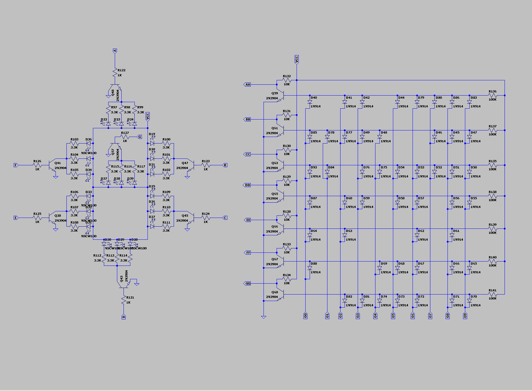
One thing I know I need for a ring counter is a decimal to 7-seg decoder. Because only one input is active to select the display digit, it is much simpler than a BCD decoder and can be implemented as a diode array with drive transistors.

- 7seg_decode_sch.png (38.04 KiB) Viewed 81550 times
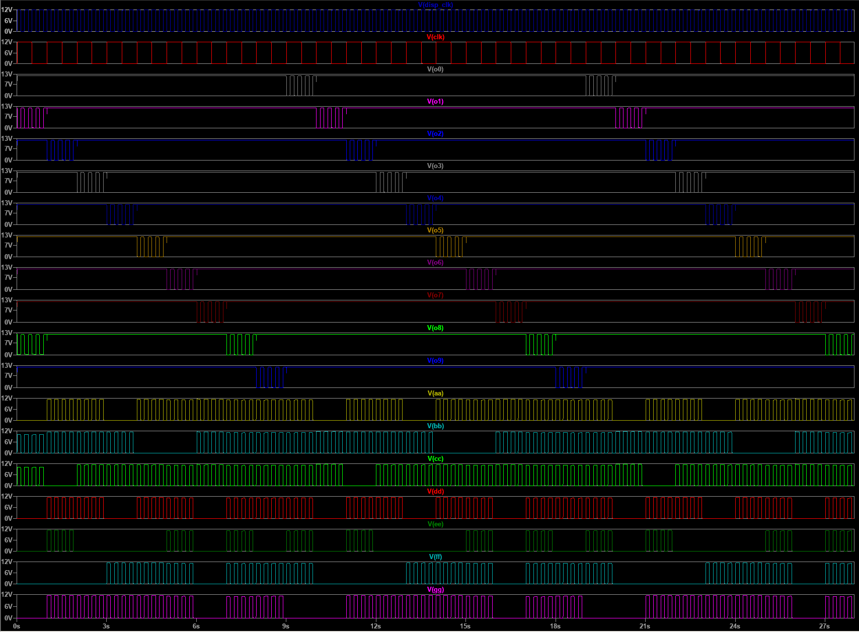
Here is the waveform of the decoder in operation. Note that the inputs are actually being toggled in what looks like a weird way. That is a multiplexing clock that I was testing. I left it in because it makes it much easier to identify the segment states than just the normal high/low signal state.

- 7seg_decode.png (53.18 KiB) Viewed 81550 times
One interesting thing to note about this simulation is that at the start, both stage 1 and stage 8 are active. After the first clock tick, the counter corrects itself and starts counting properly. The actual circuit will start in some indeterminate state and when powered up, it will start counting from a random count. The Spice simulation actually emulates this properly. It happens to start counting a 2 in this simulation, but the starting point varies in each simulation run.
--SS